Overview
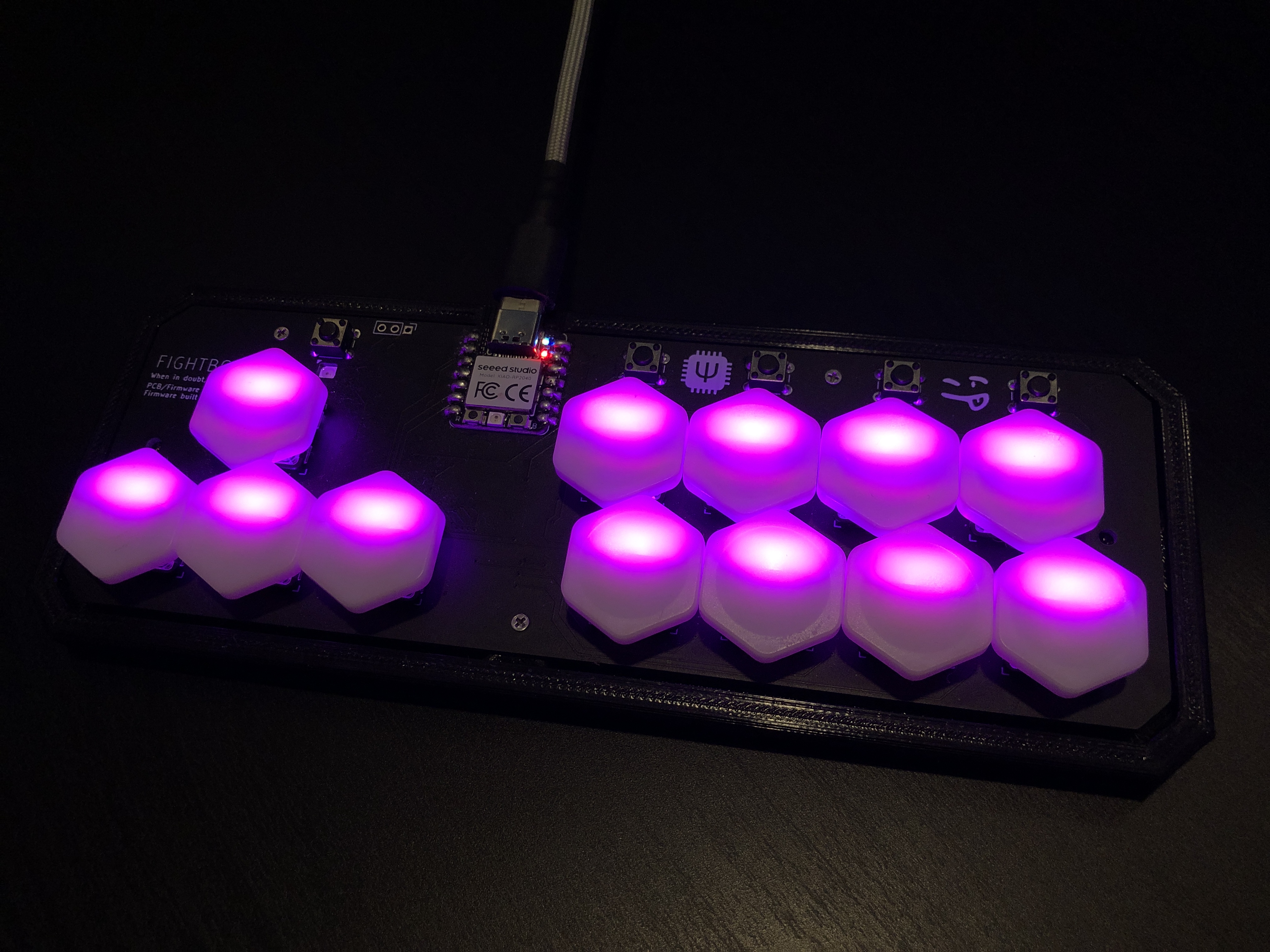
While v1 was a small step into keyboard design, v2 is a giant leap for an upgrade! Not only is v2 about a third the size of v1, but it now includes customizable LED functions, switchable layers, EEPROM storage for remembering states after power loss, and an extra button to customize functions on the fly. Since this is an upgrade, the specs are the same of those of v1 (written in C using QMK firmware, PCB designed in KiCAD, XIAO RP2040) with the figuratively massive change from a throughhole MCP23018 to a literally miniscule surface mount I/O expander. v2 also uses 13 SK6812-MINI LEDs, a TXB0108 level shifter, and a new (custom) keyswitch footprint that allows for soldering on either MX Cherry or Choc hotswap sockets. All of this was worked on during November and December of last year, while the case seen above was mainly worked on in January.
Project Purpose
This project is the direct upgrade to v1, and some of the features had been planned even before v1 was finished. The main obstacle was the LED circuitry, as not only do they more than double the complexity of the circuit design, but they require 5V for power, which the RP2040 has issues supplying, but can be solved by adding a level shifter to the circuit.
Once these issues were solved, the main philosophy of the PCB design was to reduce the overall size, as v2 is meant to be a portable controller. The first step of this was to change component model, as the MCP23018-E/SP was the largest component on the previous design, so I swapped to the E/SS model, which is not only surface mount, but about one fourth of the size. This came with an issue though: the leads were so small, the PCB manufacturer told me they could not place the solder bridge for the part! Luckily, soldering was still possible, just slightly more complicated, so no changes to the design needed to be made.
![]()
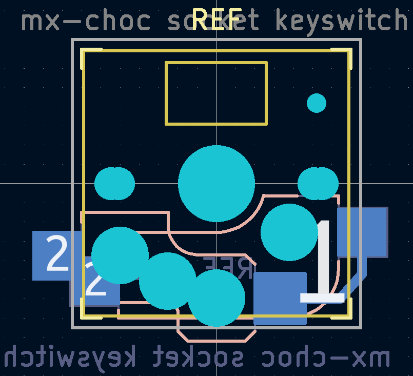
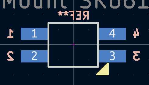
Speaking of component footprints, in order to fit both MX and Choc sockets, I had to create a custom footprint that combined the separate footprints of both of the sockets, with some edits for compatability. Not only that, but I also had to create a completely new footprint for the LEDs, as there was no secure or reliable source for one from the online store I purchased them from. Nonetheless, this was a great chance to begin learning the intricacies of component footprint design, and luckily, both custom footprints worked flawlessly, including the LED footprint which required a rectangular cutout through the entire PCB shaped for the LED body to fit through. I was able to plan for enough tolerance for the LEDs to easily fit into the cutout without enough possible movement to affect PCB assembly.
This project was a fantastic opportunity to test my soldering abilities, and I was definitely throwing myself into the deep end. I had little SMT soldering experience, and both the I/O expander and level shifter were much smaller than any part I had ever worked with. Luckily, with admittedly a few mistakes and retries, I was able to fully complete five full boards using both socket types and I now feel much more confident in my soldering skills.
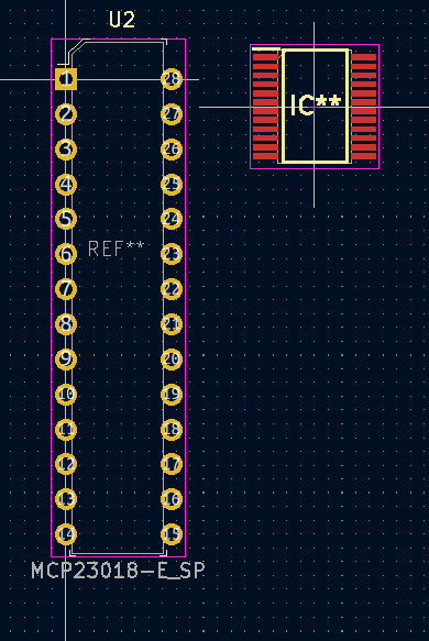
Comparison of previous MCP model (left) to current model (right)
Pictures of the Project
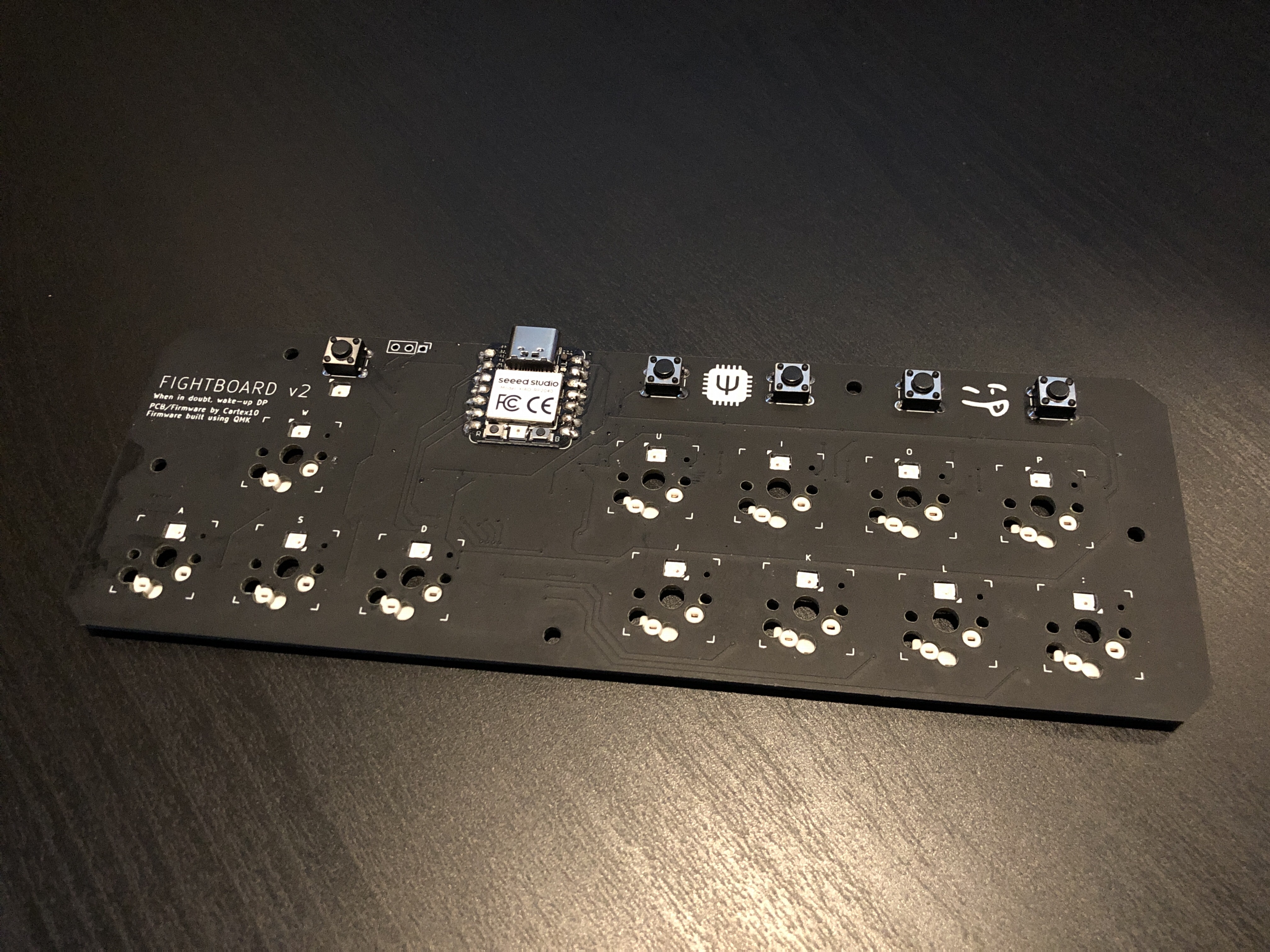
The board without switches, with MX sockets
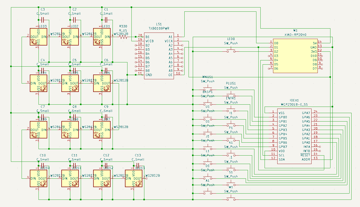
Circuit diagram in KiCAD
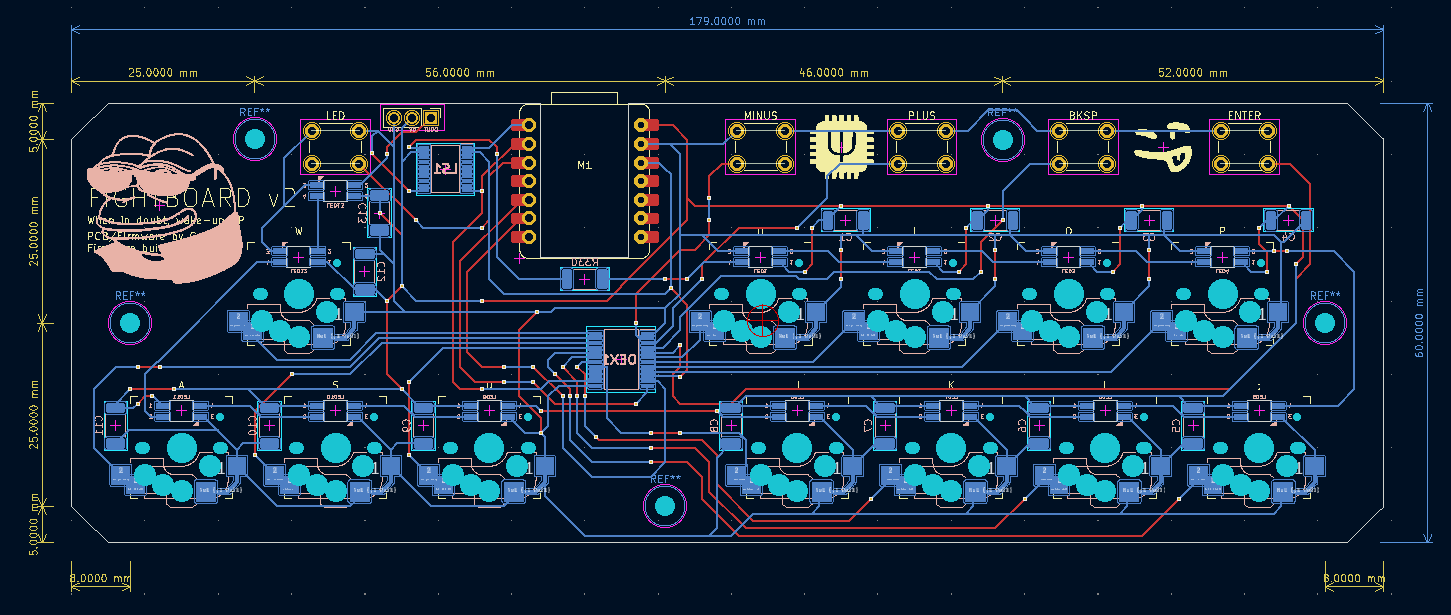
PCB in KiCAD
File Overview
matrix.c
This file has grown a lot in the upgrade, particularly in order to support optional input handling. Without getting too off topic, the keyboard has a software toggle to handle opposing directional inputs (holding up and down, the keyboard only uses the last pressed).
keymap.c
Seven layers have added in order to support multiple players on the same firmware, or other games with different control schemes. An RGB LED matrix has also been added for the SK6812-MINIs.
v2.c/h
This file handles core functions to the keyboard, such as the custom keycodes for layer selection and LED effects, EEPROM configuration/usage, and layer indication. Some functions have been taken from matrix.c for future compatability with the QMK online configurator.
Completed Objectives
v2, in relation to the design of the main board, is a complete success. Not only is every planned feature available and ready on the current PCB design, but it has been designed with future additions in mind, and some have already been successfully implemented! The upgrade exceeded intial expectations and ideas, and although the case is still work in progress, the main effort of the PCB is complete for this version.